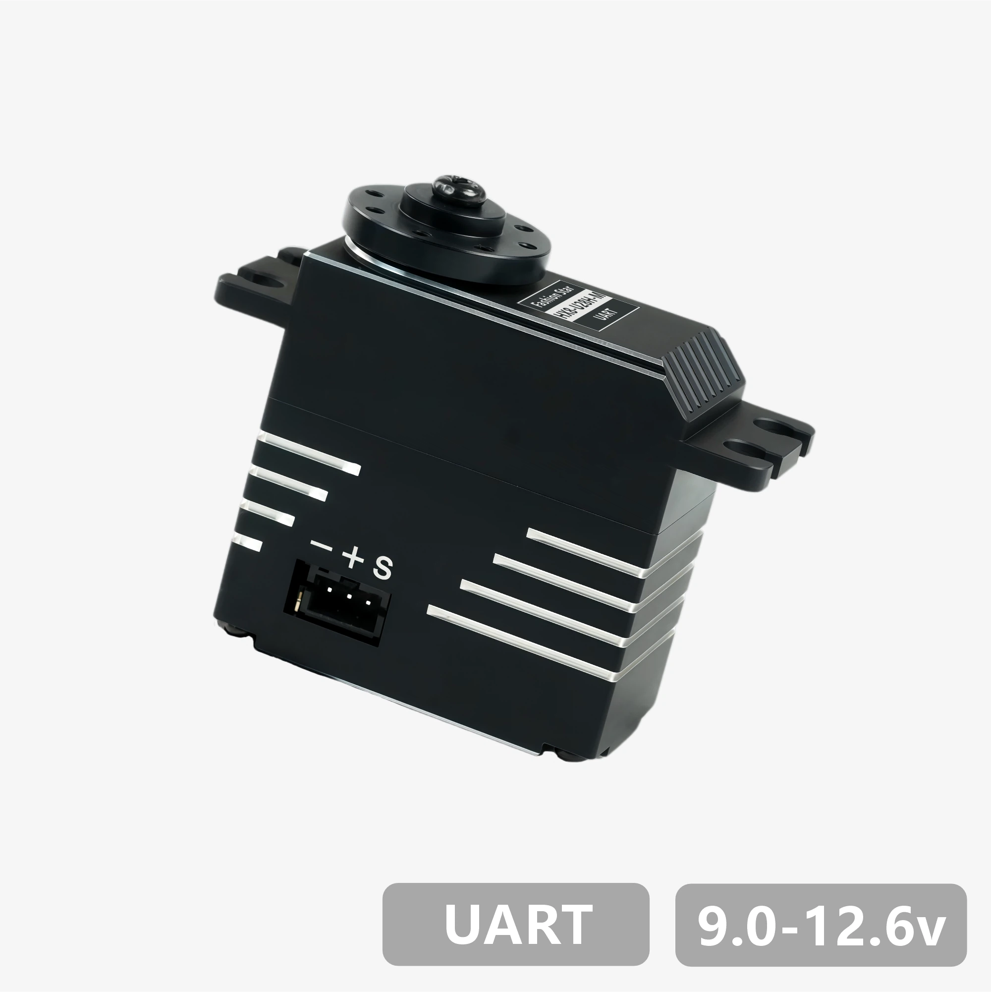
Product Datasheet - HX8-U26H-M
product-primary-taobao
HA8-U25-M
RA8-U25-M

HA8-U25H-M
RA8-U25H-M
HA8-U35-M
RA8-U35-M

HA8-U35H-M

RA8-U35H-M

HX8-U45H-M

RX8-U45H-M

HX8-U28H-M
RX8-U28H-M
HX8-U29H-M

RX8-U29H-M
HX8-U50H-M

RX8-U50H-M
HX8-U51H-M
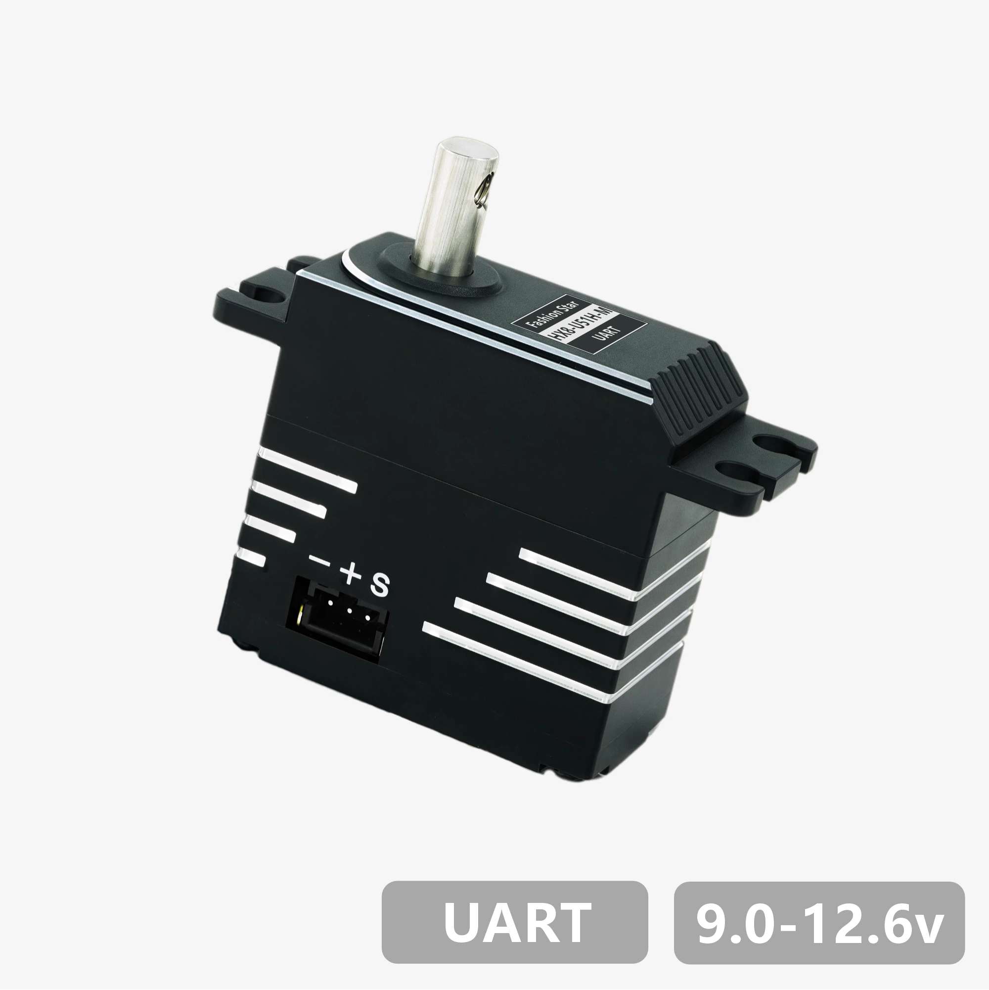
RX8-U51H-M

RX18-U100H-M
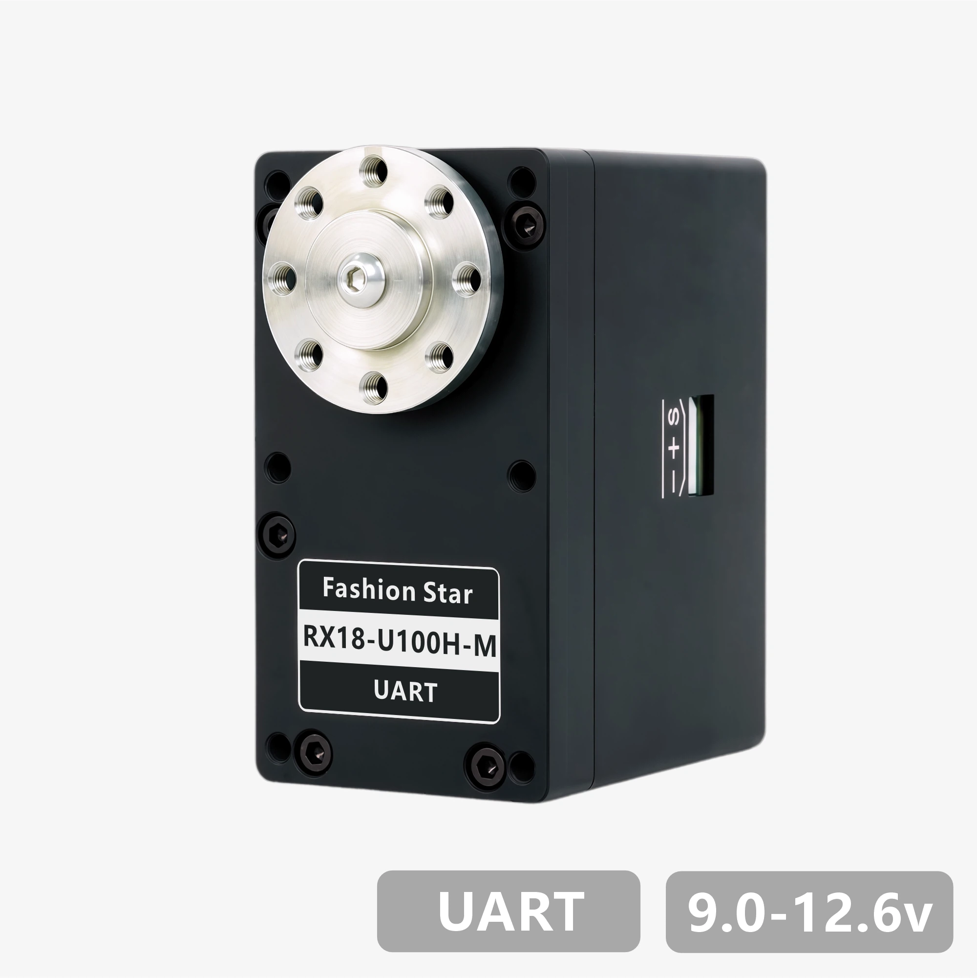
RX18-U101H-M

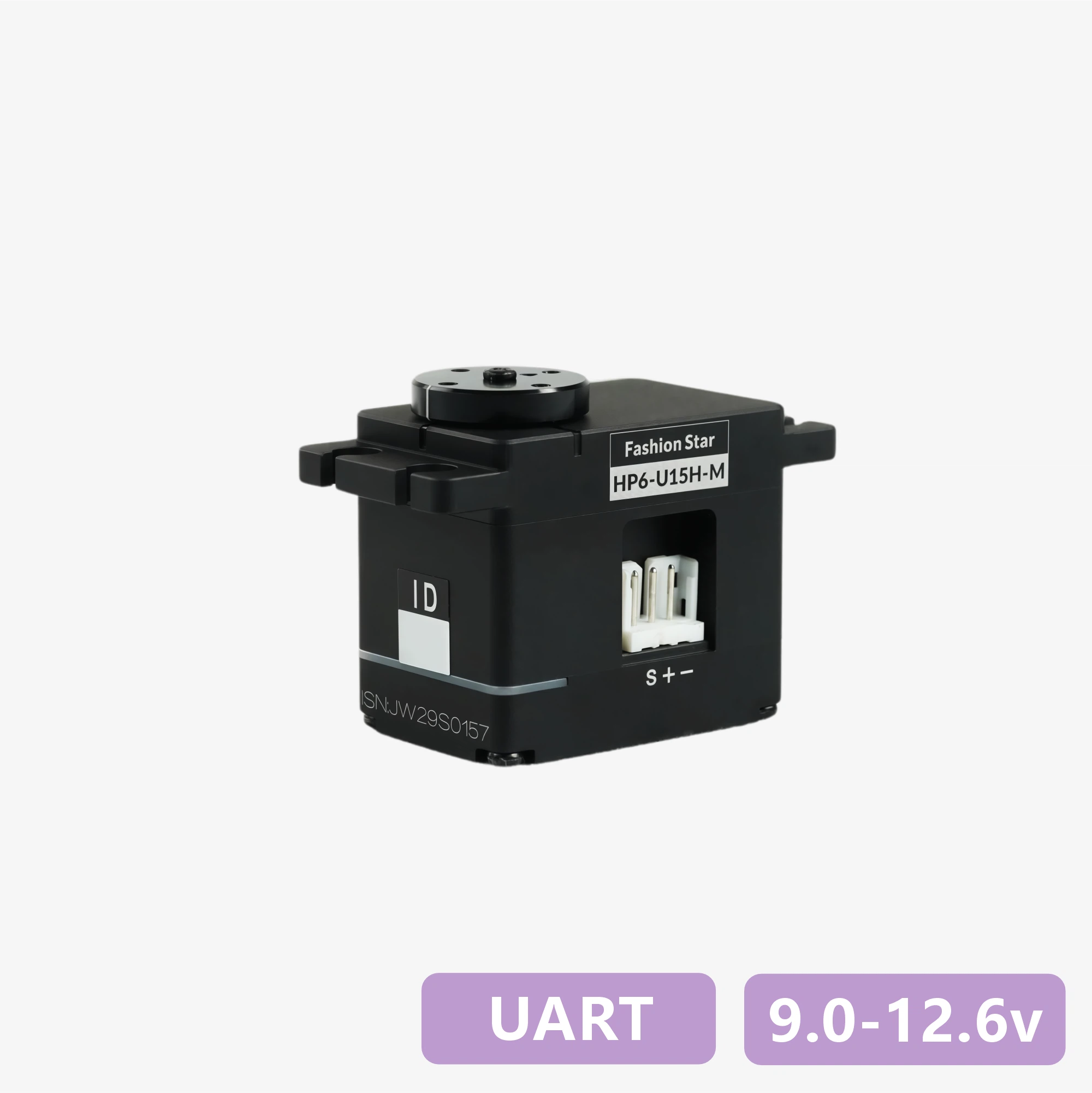
HP6-U15H-M
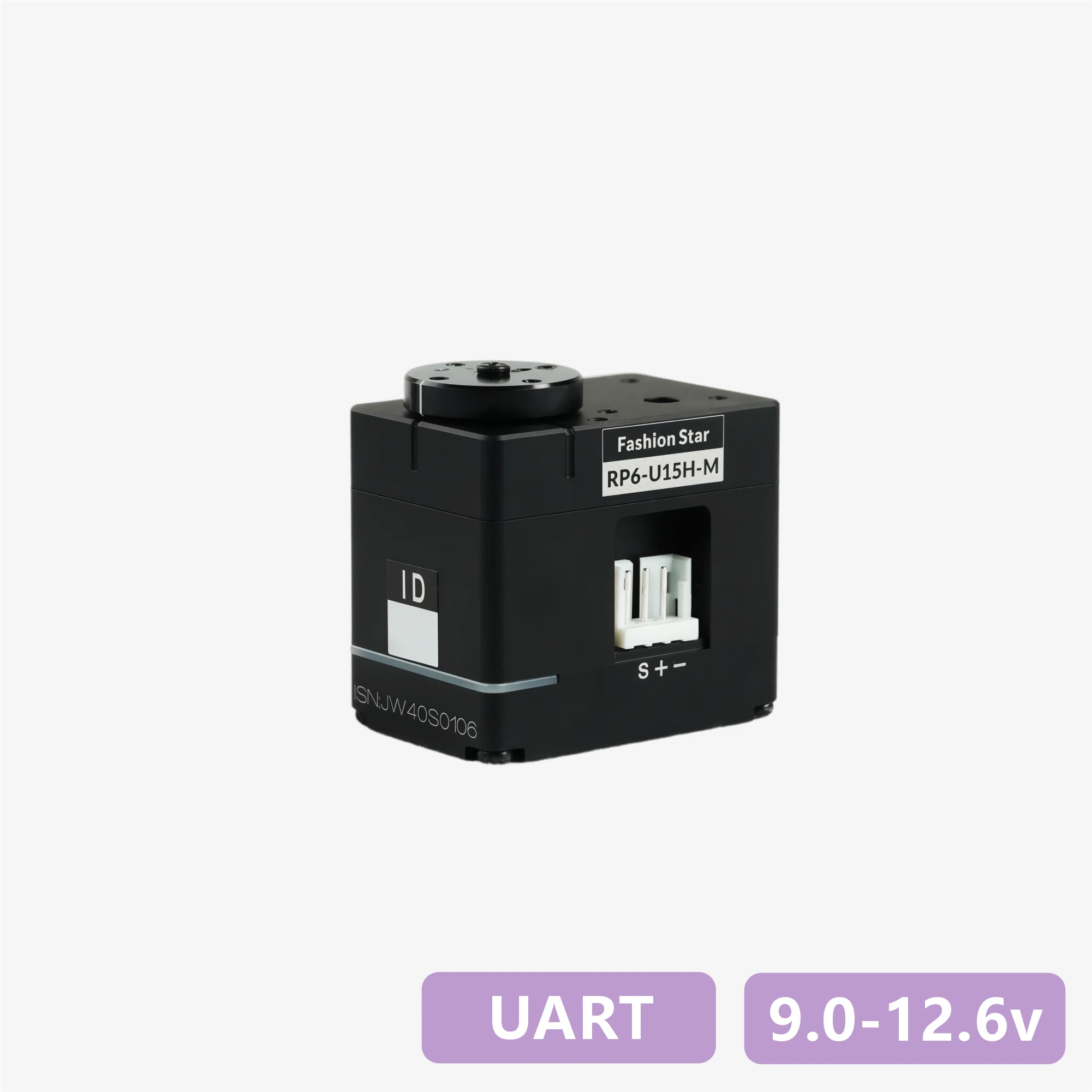
RP6-U15H-M
RP6-U12H-M
RX6-U12H-M
RP6-U18H-M
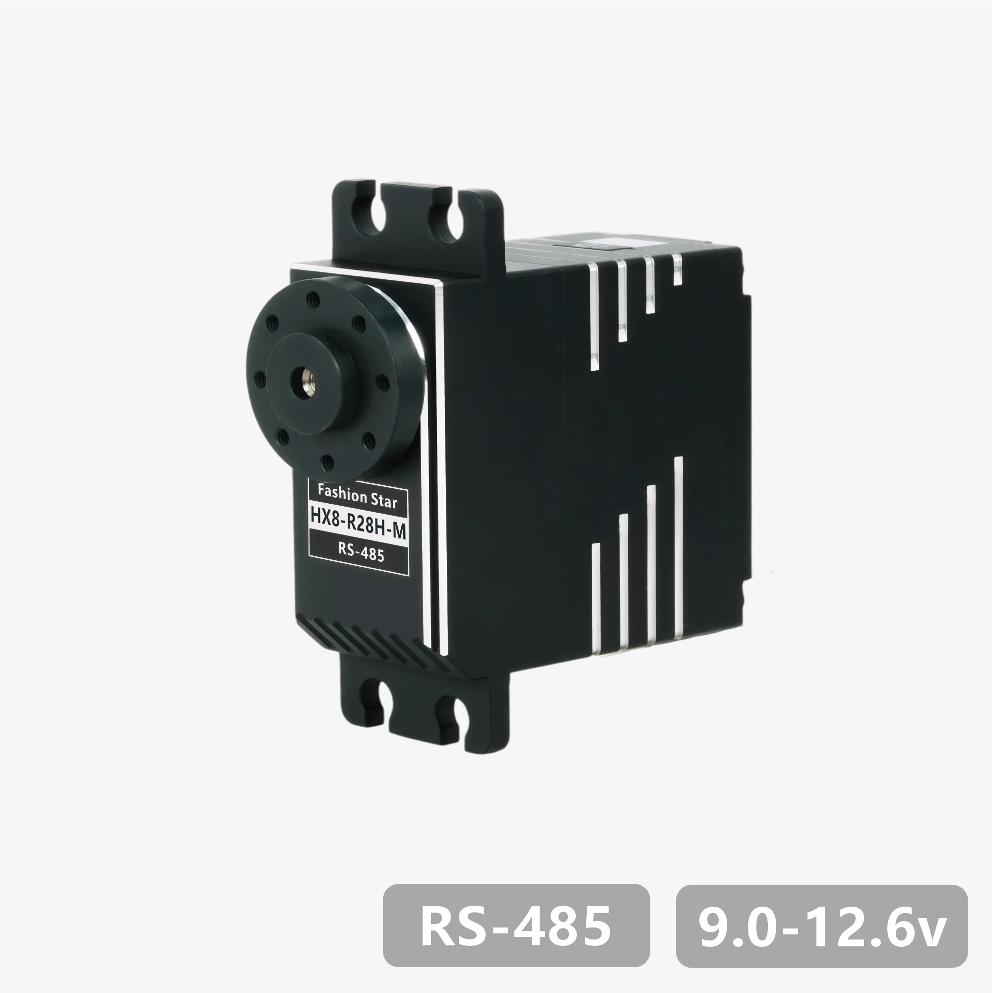
HX8-R28H-M
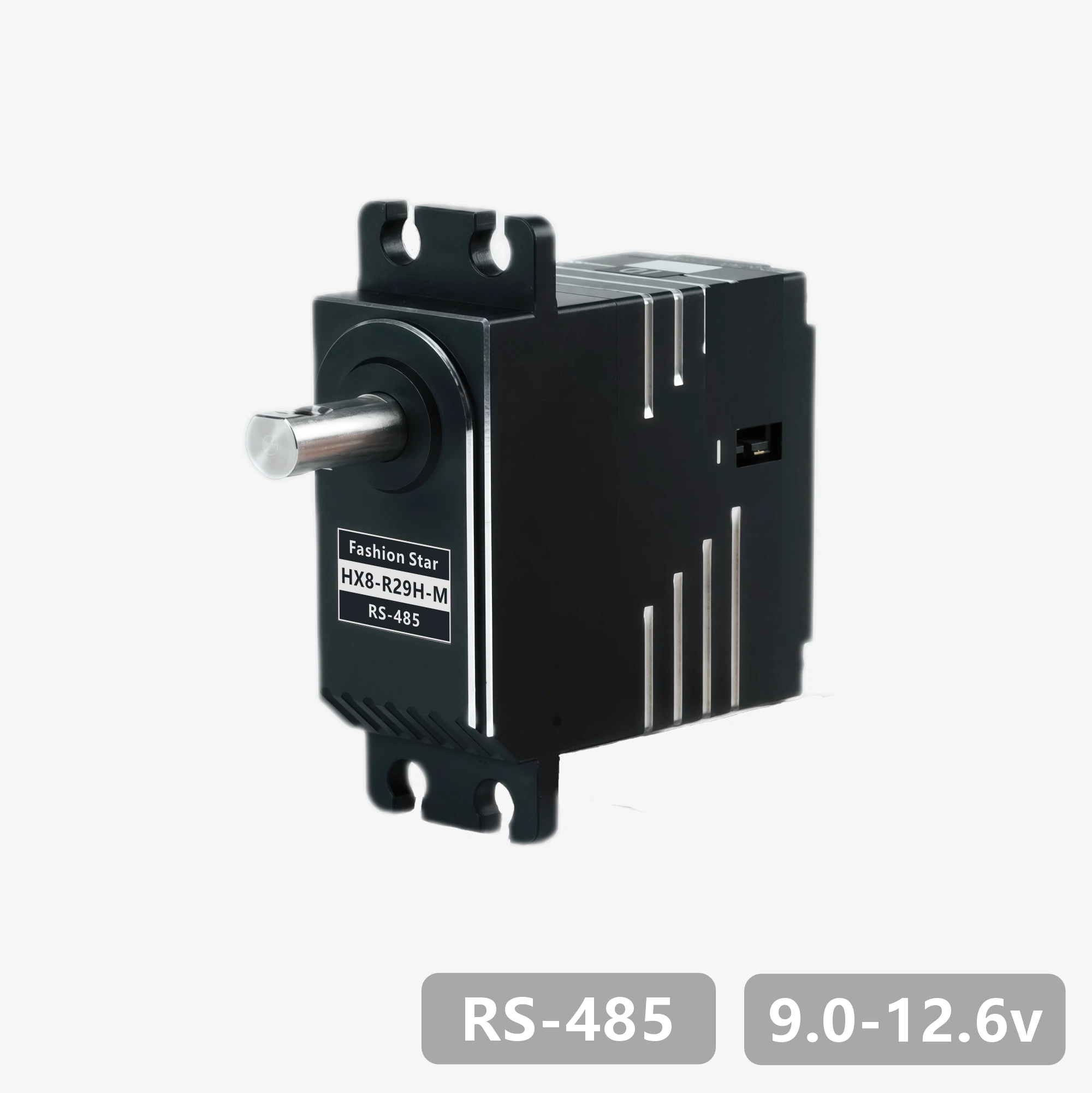
HX8-R29H-M
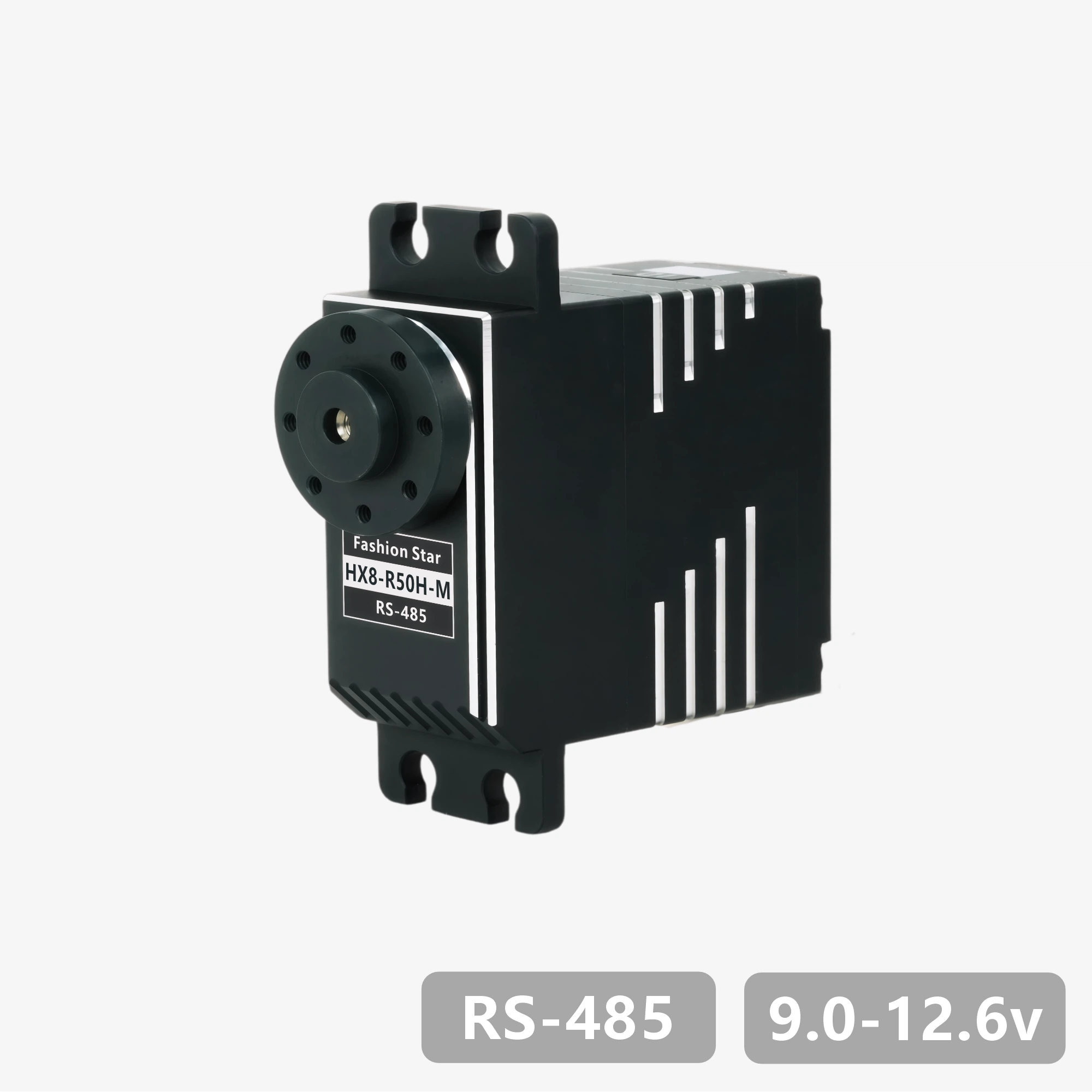
HX8-R50H-M
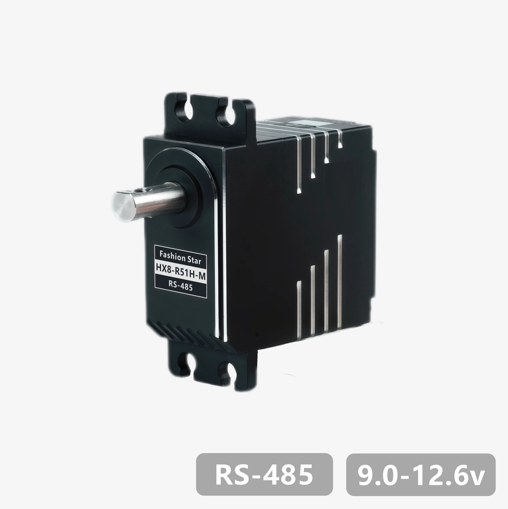
HX8-R51H-M
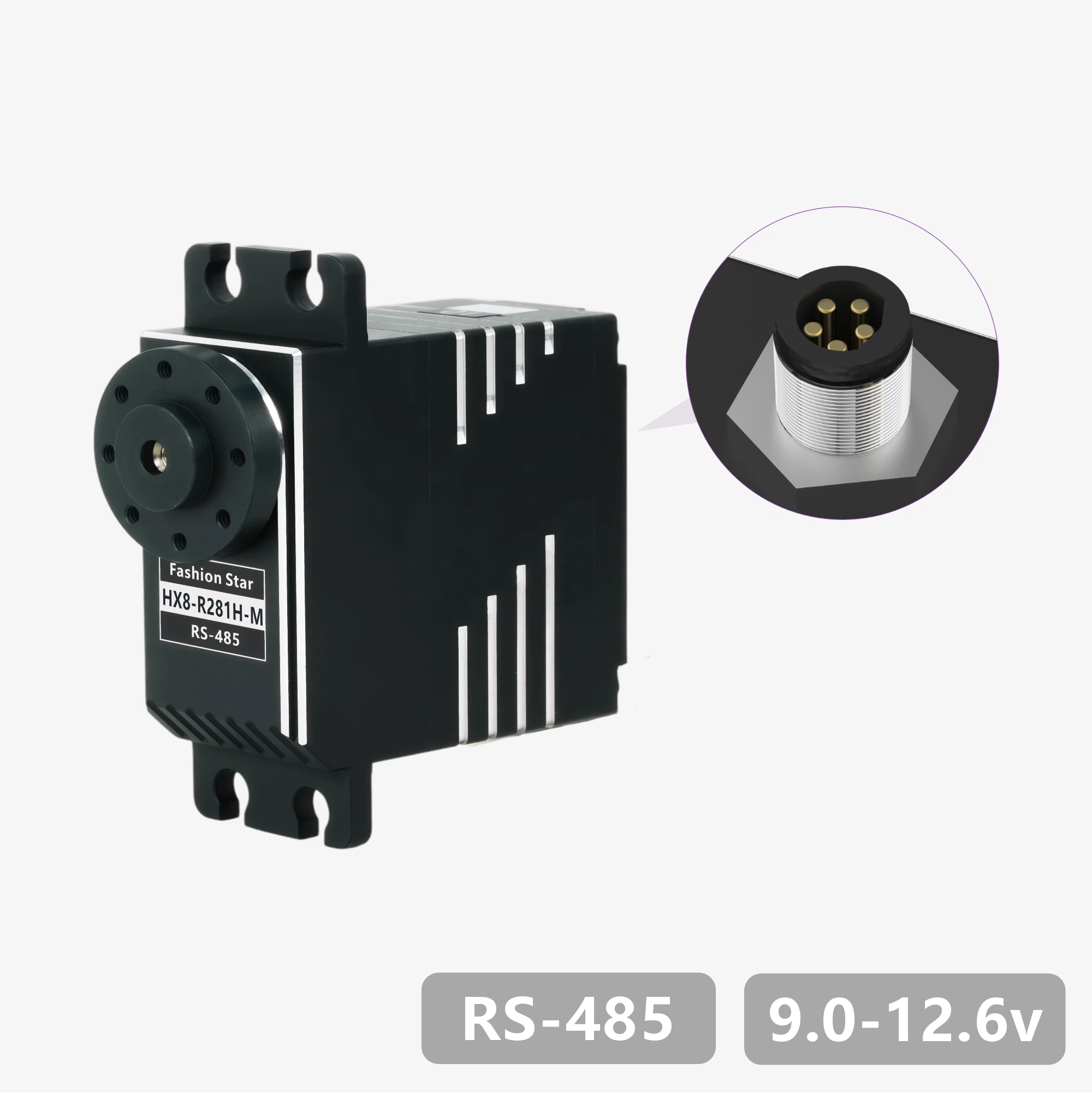
HX8-R281H-M
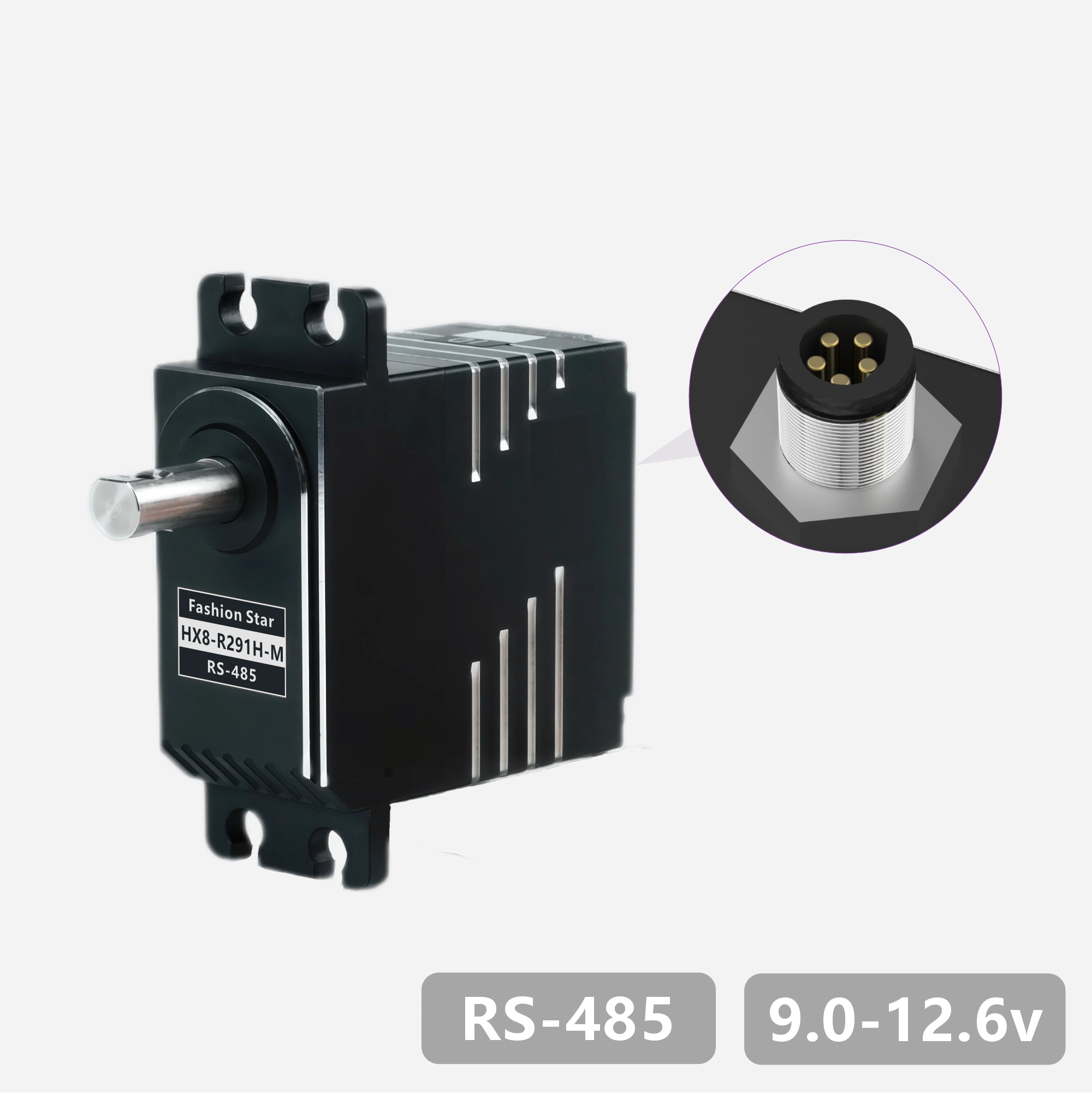
HX8-R291H-M
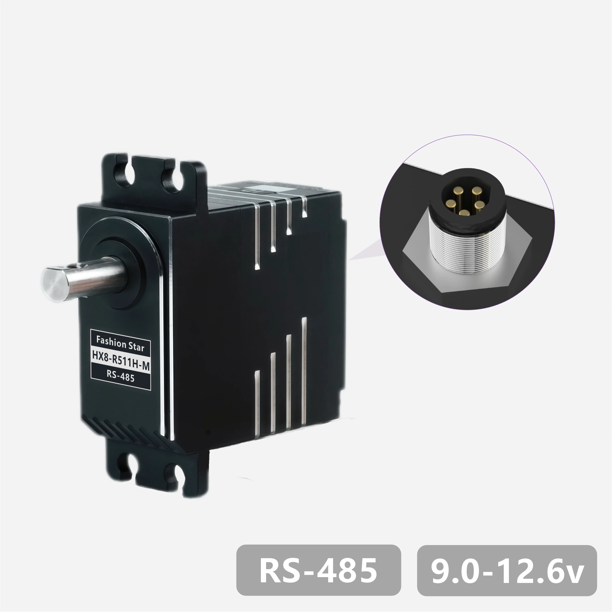
HX8-R511H-M
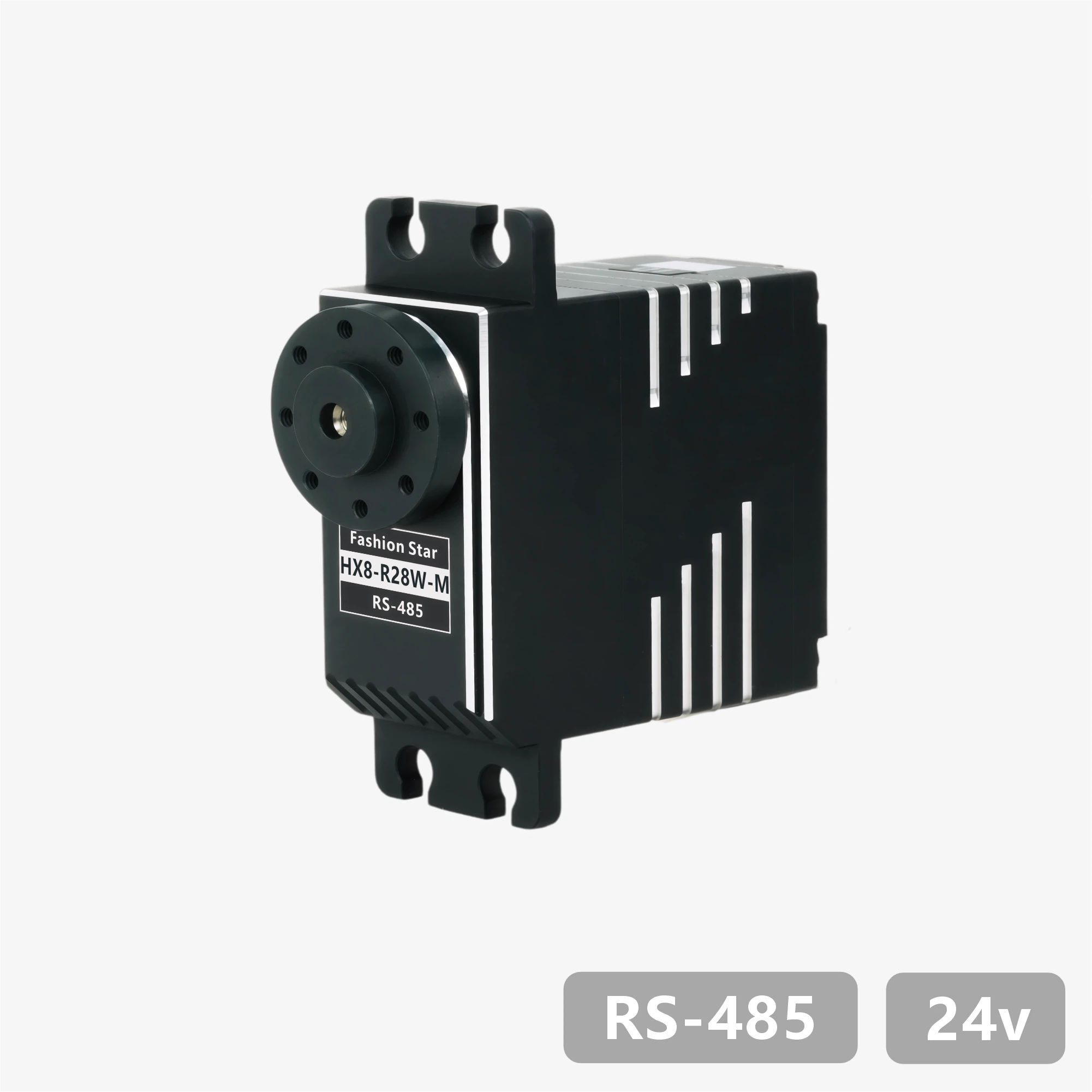
HX8-R28W-M
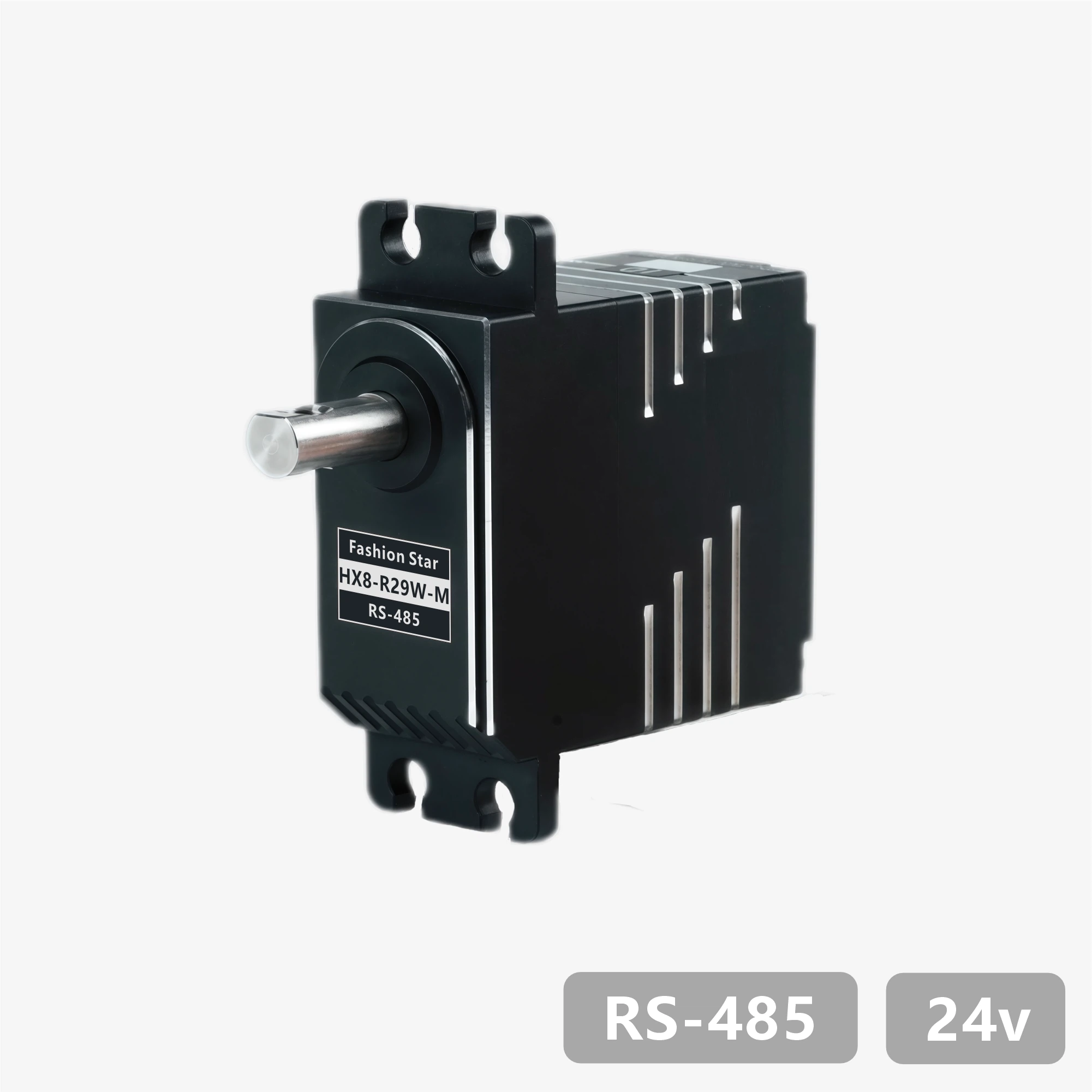
HX8-R29W-M
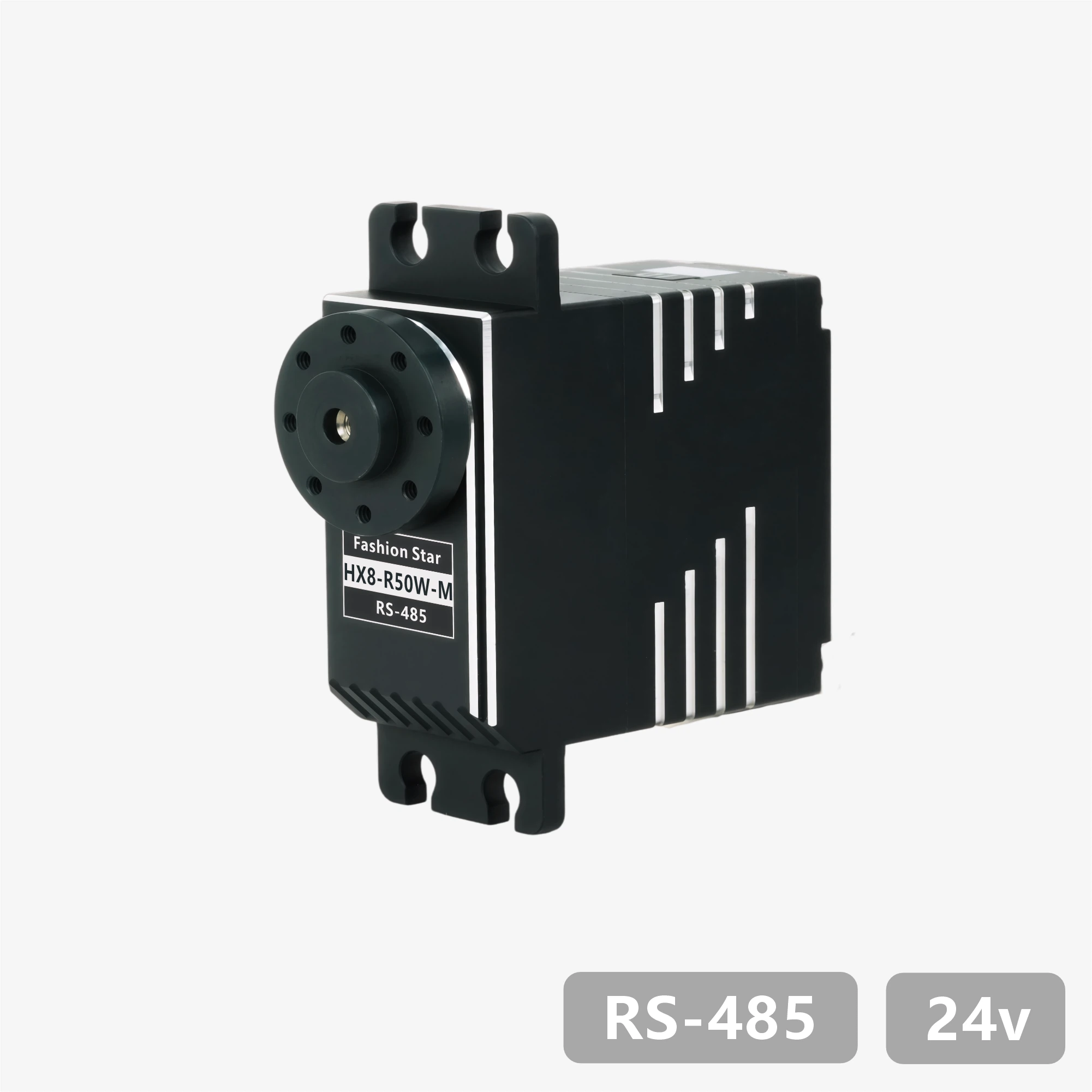
HX8-R50W-M
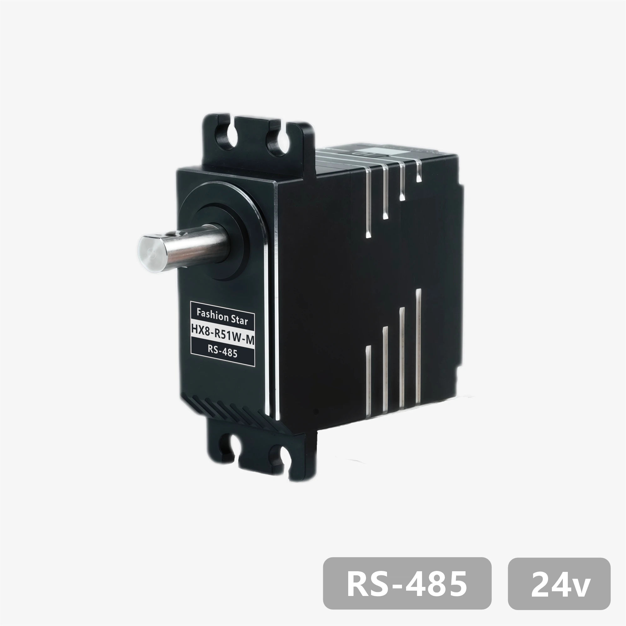
HX8-R51W-M
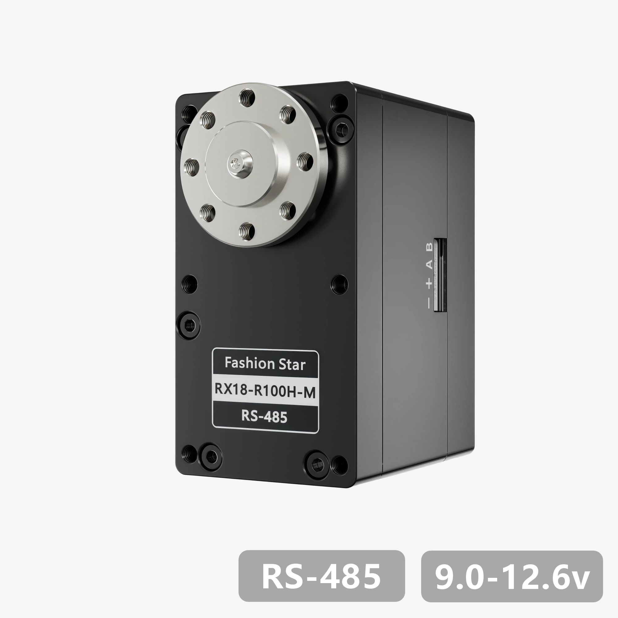
RX18-R100H-M
RX18-R101H-M

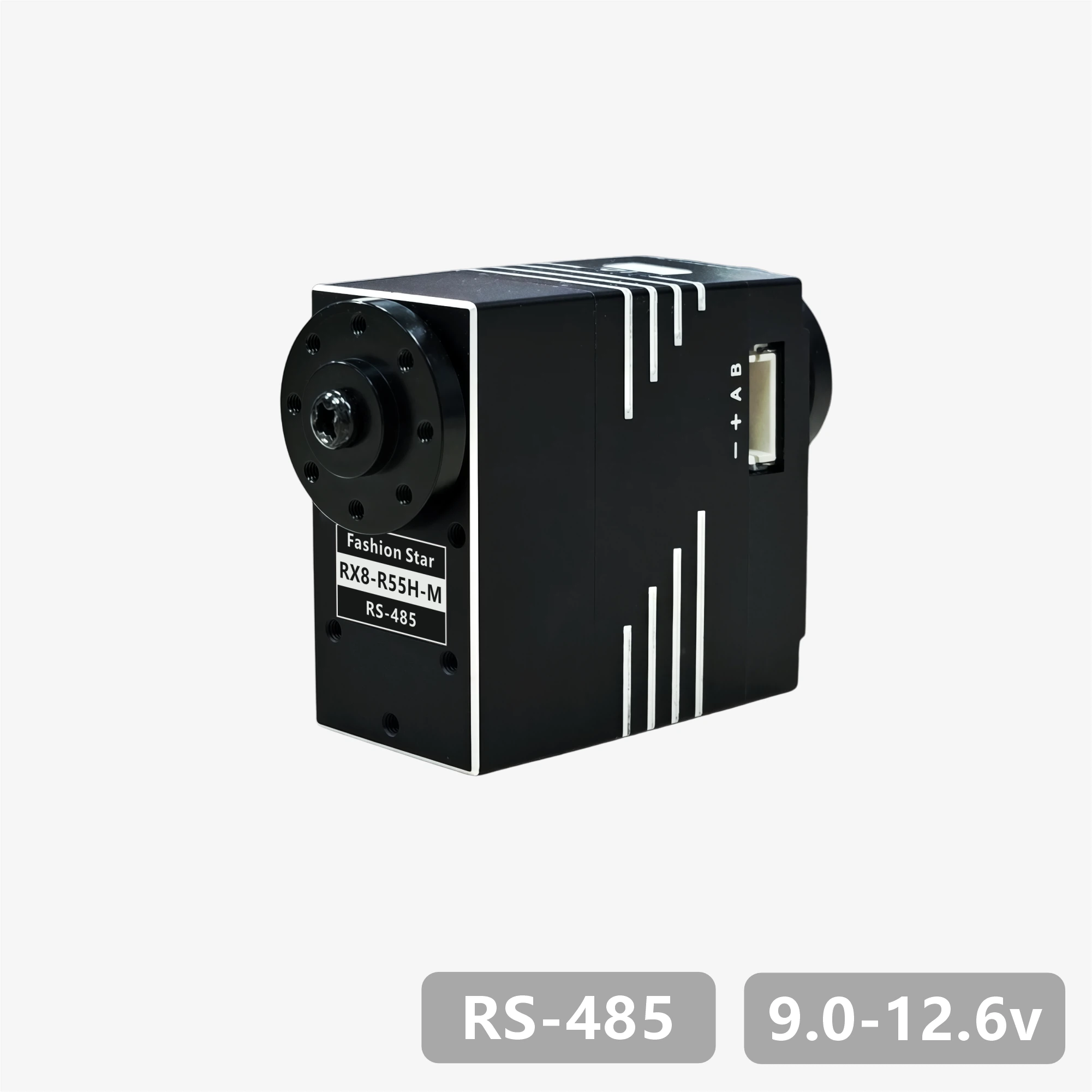
RX8-R55H-M
1. Product Features
- Features a brushless motor / stainless steel gear train design
- UART bidirectional communication with baud rates up to 1 Mbps, supporting position and status readback
- 12-bit absolute position encoder (4,096-step resolution) with configurable zero point
- Multi-turn angle control range up to ±368,640° (1,024 turns), with power-off angle memory
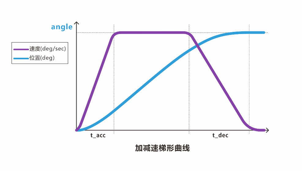
- Built-in trapezoidal acceleration/deceleration algorithm for smooth motion control
- Supports three stop modes: hold torque / release torque / damping control
- Integrated protection for temperature, voltage, stall, power, and current, with intelligent power limiting
- Includes PC configuration software with firmware upgrade support
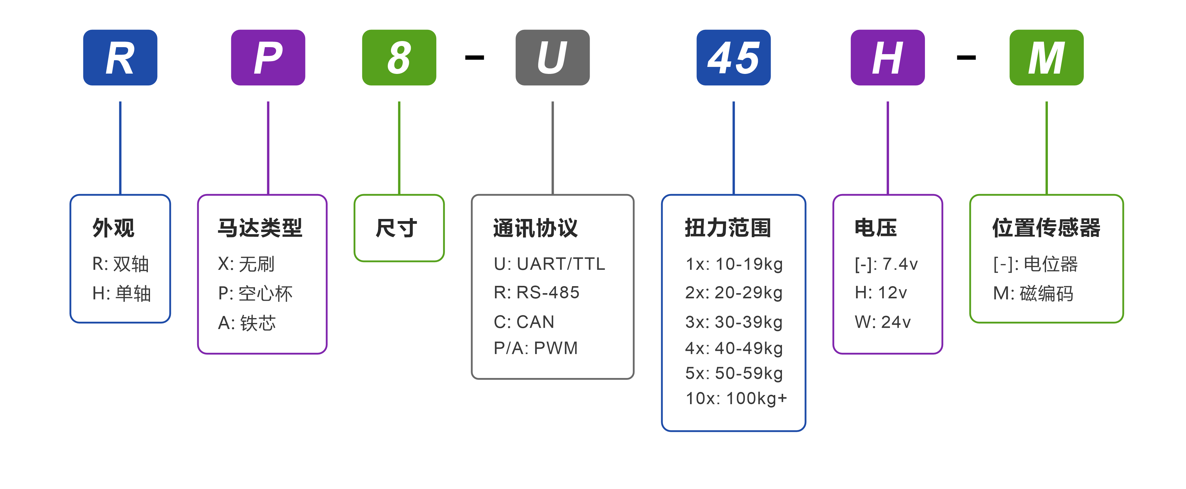
2. Model Definition
3. Specifications
3.1 基础参数
| Parameter | Value |
|---|---|
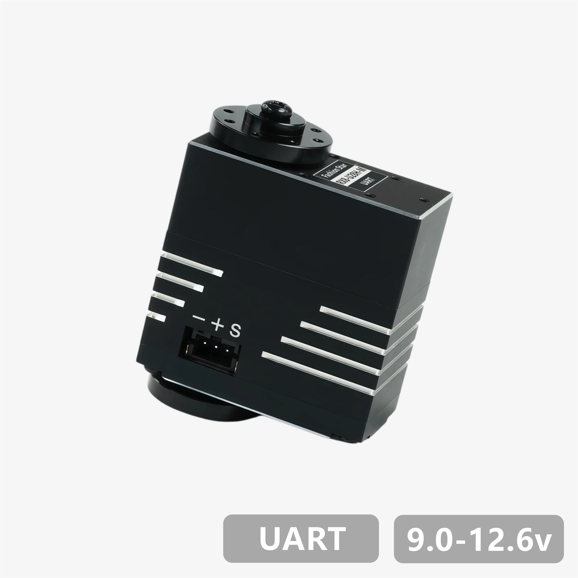
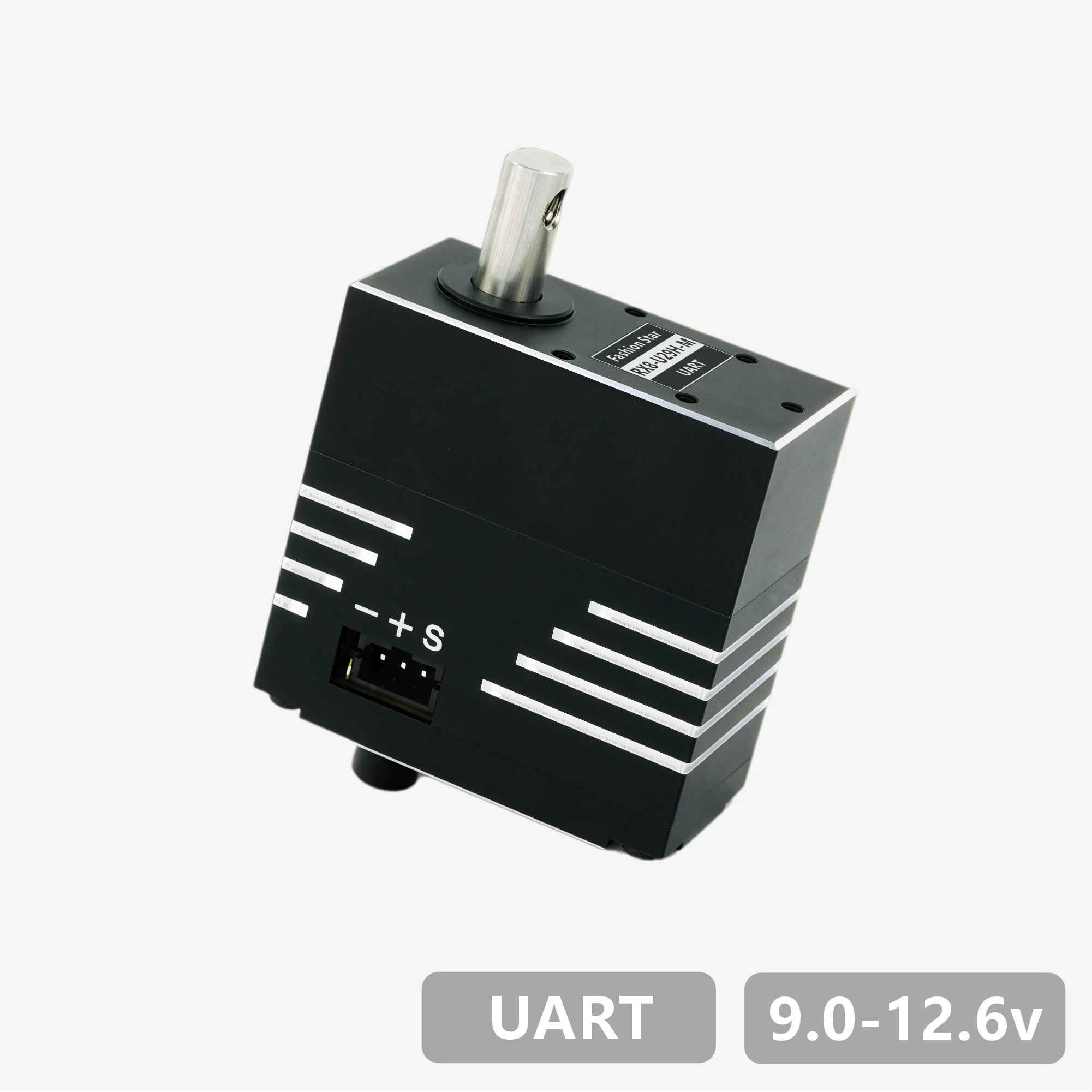
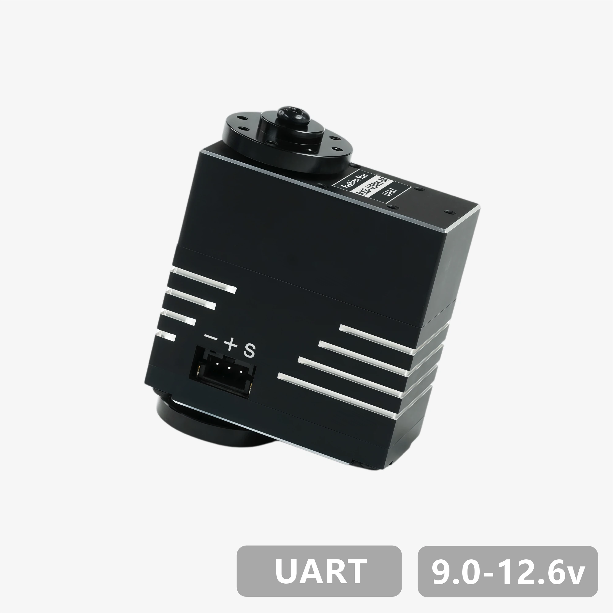
| Operating Voltage | 9.0~12.6 V |
| Motor Type | Brushless Motor |
| Position Sensor | 12-bit 非接触式绝对值编码器(磁编码) |
| Resolution | 4096 阶 / 360°(0.088°) |
| Effective Range | ±180°(单圈)/±368,640°(多圈) |
| Processor | 32-bit MCU |
| Communication | UART / TTL Half-duplex |
| Baud Rate | 9,600 bps ~ 1 Mbps |
| ID Range | 0 ~ 254 |
| Gear Ratio | 173:1 |
| Gear Material | Full-metal stainless-steel gear set |
| Output Shaft Spec | 不锈钢 / Ø6 mm / 25T |
| Housing Material | 全铝合金 |
| Connector Type | PH2.0 – 3Pin |
| Dimensions / Weight | 40 × 20 × 40 mm / 83 g |
| Operating Temperature | -10~60 ℃ |
| Operating Modes | Single-turn Position | Multi-turn Position | Damping Mode |
3.2 特性参数(@12V)
| Parameter | Value |
|---|---|
| Static Stall Torque | 2.74 N·m(28kg·cm) |
| Max Dynamic Torque | 1.18 N·m(12kg·cm) |
| Rated Torque | 0.44 N·m(4.5kg·cm) |
| No-load Speed | 142 rpm(0.070 s / 60°) |
| Rated Speed | 116 rpm(0.086 s / 60°) |
| Peak Current | 5.5 A |
| No-load Current | <300 mA |
| Standby Current | <40 mA |
| Axial | 20 N |
| Radial | 40 N |


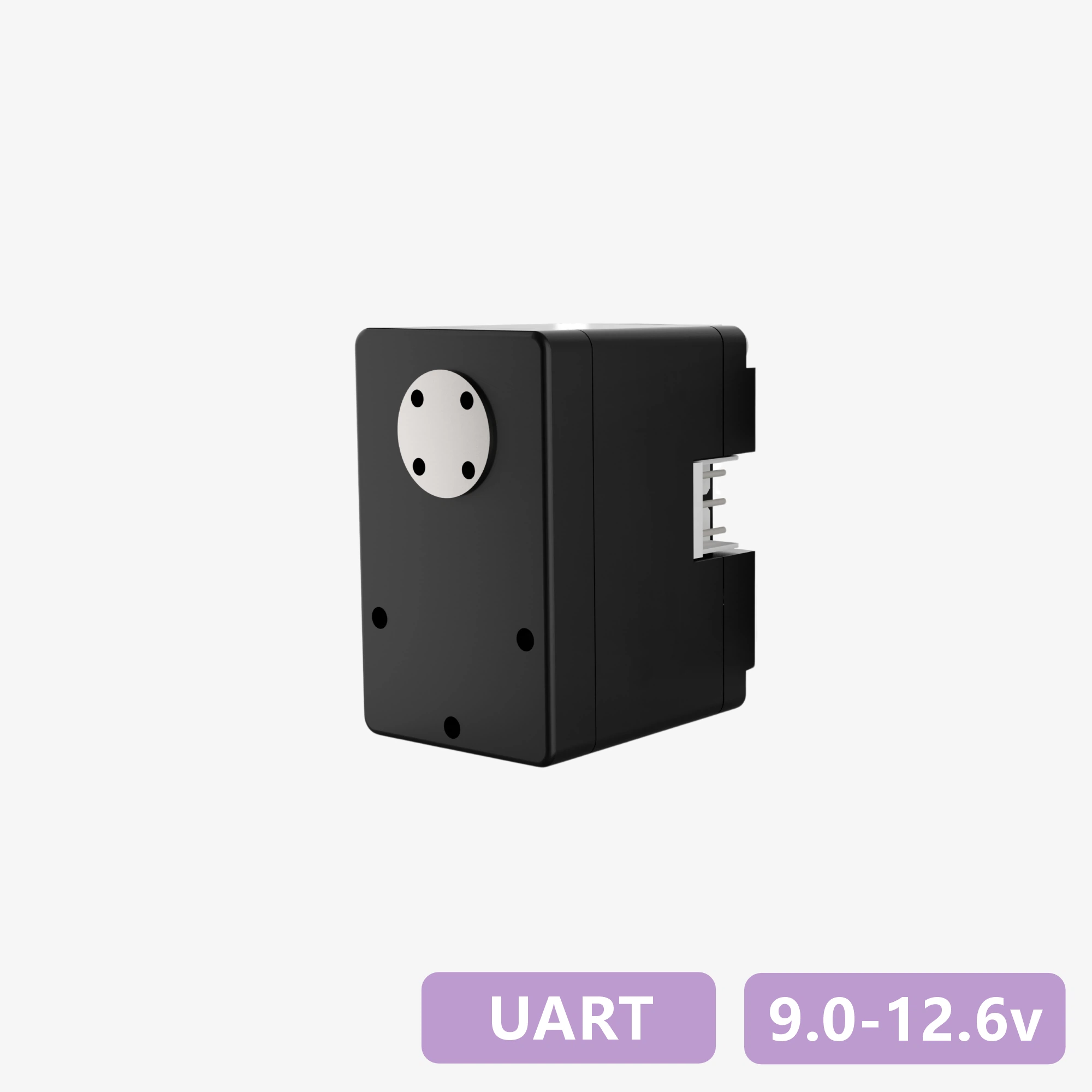
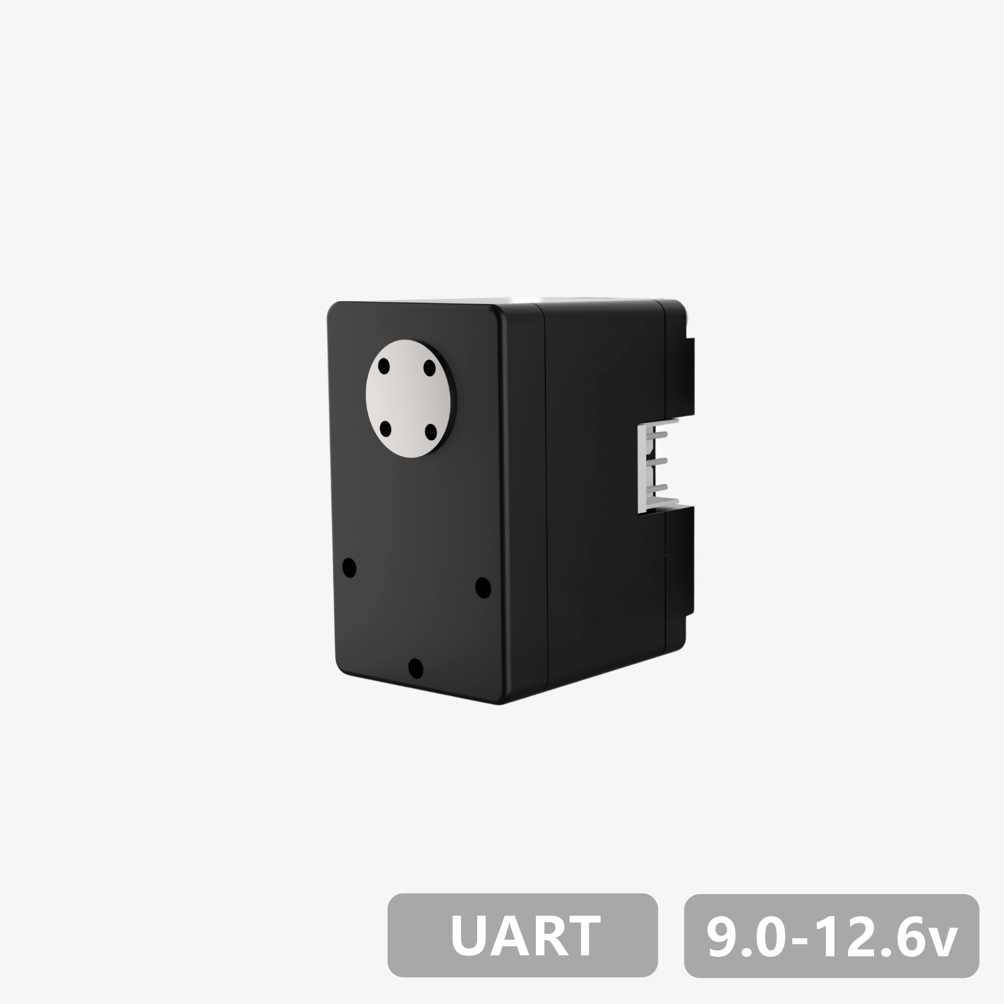
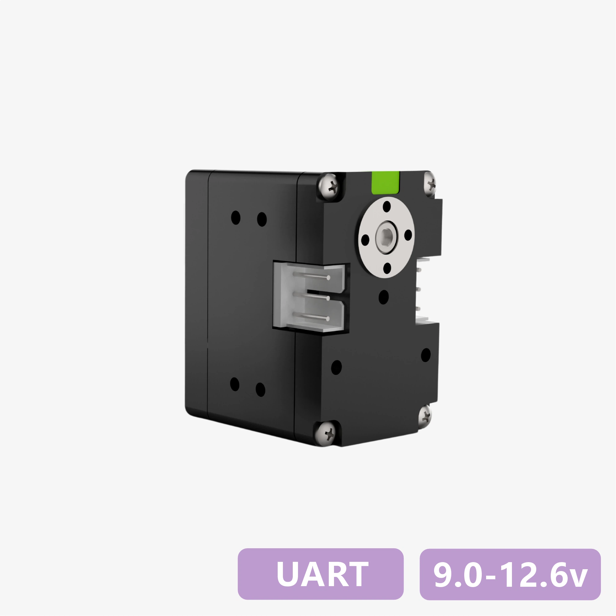
4. 外观尺寸与安装
文件下载: PDF | STEP | DWG| 更多配件图纸


5. Interface & Wiring


6. Development Environment & SDK
Provides SDKs and example projects for mainstream control boards, programming languages, and robot frameworks, supporting rapid validation, feature development, and system integration.
| Platform / Environment / Language | Compatible Models / Content |
|---|---|
| Arduino | |
| ESP32 | |
| STM32 | |
| Raspberry Pi (Python) | |
| Programming Languages | |
| Robot Frameworks |
7. Protection Functions
Bus servos integrate multiple protection mechanisms, including temperature, voltage, stall, power, and current protection. The current protection state can be identified through the status flags.
| Temperature Protection |
|---|
|
| Stall Protection |
|---|
|
| Power Protection |
|---|
|
| Voltage Protection |
|---|
|
| Current Protection |
|---|
|
Warning
- After voltage protection is triggered, the servo will resume operation only after power is removed and restored.
- Stall / power / current protection are used to prevent overload damage. Excessively high thresholds may cause protection to fail.
- If temperature or current protection is triggered frequently, reduce the load or improve cooling and power supply conditions.
Note
- The default threshold for temperature protection is 70°C.
- Default voltage protection ranges: 7.4 V version: 6.0-8.4 V / 12 V version: 9.0-12.6 V / 24 V version: 20.0-25.2 V.
- Current protection can be combined with stall / power protection. When the PC configuration software does not trigger the first two logic paths, current protection serves as the final hardware safeguard.
8. Commands & Protocol
Bus servos use the UART/RS485 bus communication protocol, based on half-duplex asynchronous serial communication and a command-response mechanism. This supports command transmission and status readback between the host controller and multiple servos, while bus addressing and device identification are completed through a unique ID assigned to each servo (default ID = 0).
8.1 Control Commands
- Frame format: 8 data bits + 1 stop bit (no parity).
TxDandRxDcannot operate simultaneously. Only one device may transmit at a time, while all others remain in receive standby.- A 5-10 ms interval is recommended between consecutive commands.
| Command Name | Command ID | Response Packet Type |
|---|---|---|
| Communication Test | 01 (0x01) | Fixed |
| Simple Single-turn Angle Control | 08 (0x08) | Configurable |
| Advanced Single-turn Angle Control (Time-based) | 11 (0x0B) | Configurable |
| Advanced Single-turn Angle Control (Speed-based) | 12 (0x0C) | Configurable |
| Current Single-turn Angle Readback | 10 (0x0A) | Fixed |
| Simple Multi-turn Angle Control | 13 (0x0D) | Configurable |
| Advanced Multi-turn Angle Control (Time-based) | 14 (0x0E) | Configurable |
| Advanced Multi-turn Angle Control (Speed-based) | 15 (0x0F) | Configurable |
| Current Multi-turn Angle Readback | 16 (0x10) | Fixed |
| Turn Count Reset | 17 (0x11) | Configurable |
| Damping Control | 09 (0x09) | Configurable |
| Stop Command | 24 (0x18) | Configurable |
| Synchronous Command | 25 (0x19) | None |
| Asynchronous Write Command | 18 (0x12) | None |
| Asynchronous Execute Command | 19 (0x13) | None |
| Data Read | 03 (0x03) | Fixed |
| Data Monitoring | 22 (0x16) | Fixed |
| Set Zero Point | 23 (0x17) | Configurable |
| Custom Configuration Parameters | 04 (0x04) | Configurable |
Note
By default, if a new command is received while the servo is executing the current command, the current command is interrupted immediately and the new command takes priority.
8.2 Command Packet
A command packet is the standard data structure used by the host controller to send control or query commands to the servo.
- header: fixed as
0x12 0x4C, indicating the start of a command packet. - cmd_id: the control command carried in this packet
-
length: the byte length of the following data content, used for packet parsing.
-
content: stores control parameters according to the command type, such as servo ID, target angle, motion time, power value, and others.
- checksum: the sum of all bytes modulo 256, used to verify data integrity.

8.3 Response Packet
A response packet is the standard data structure used by the servo to return execution results and related data to the host controller after receiving and validating a command packet.
Its overall structure is consistent with the command packet, with differences only in the start marker and data-content definition.
- header: fixed as
0x05 0x1C, indicating the start of a response packet. - cmd_id: the control command carried in this packet
-
length: the byte length of the following data content, used for packet parsing.
-
content: returns the execution result or related data according to the command type, such as current angle, voltage, temperature, version, and readback parameters.
- checksum: the sum of all bytes modulo 256, used to verify data integrity.

9. Motion & Control Commands
9.1 Communication Test
Send a communication test command to the target ID and determine whether the servo is online based on the response packet.
| Command ID | Command Name | Description |
|---|---|---|
| 01 (0x01) | Communication Test | Response packet = online device ID |
9.2 Single-turn Angle Control
- Supports both time-based and speed-based control, with current position available through the single-turn angle readback command.
- Control range: ±180°, with a minimum control resolution of 0.1°.
| Command ID | Command Name | Parameters |
|---|---|---|
| 08 (0x08) | Simple Single-turn Angle Control | Target angle, motion time, operating power |
| 11 (0x0B) | Advanced Single-turn Angle Control (Time-based) | Target angle, motion time, acceleration time, deceleration time, operating power |
| 12 (0x0C) | Advanced Single-turn Angle Control (Speed-based) | Target angle, motion speed, acceleration time, deceleration time, operating power |
| 10 (0x0A) | Current Single-turn Angle Readback | Response packet = current servo angle |
9.3 Multi-turn Angle Control
- Supports both time-based and speed-based control, with current position available through the multi-turn angle readback command.
- Control range: ±368,640° (±1,024 turns), with a minimum control resolution of 0.1°.
| Command ID | Command Name | Parameters |
|---|---|---|
| 13 (0x0D) | Simple Multi-turn Angle Control | Target angle, motion time, operating power |
| 14 (0x0E) | Advanced Multi-turn Angle Control (Time-based) | Target angle, motion time, acceleration time, deceleration time, operating power |
| 15 (0x0F) | Advanced Multi-turn Angle Control (Speed-based) | Target angle, motion speed, acceleration time, deceleration time, operating power |
| 16 (0x10) | Current Multi-turn Angle Readback | Response packet = current servo angle |
9.4 Turn Count Reset / Power-off Memory
Turn Count Reset
- When the servo is in release-torque state, the turn count can be reset through the PC configuration software or a designated command, recording the current absolute position angle as the new current angle.
- After reset, the initial angle falls within the -180° to +180° range.
| Command ID | Command Name | Description |
|---|---|---|
| 17 (0x11) | Turn Count Reset | - |
Note
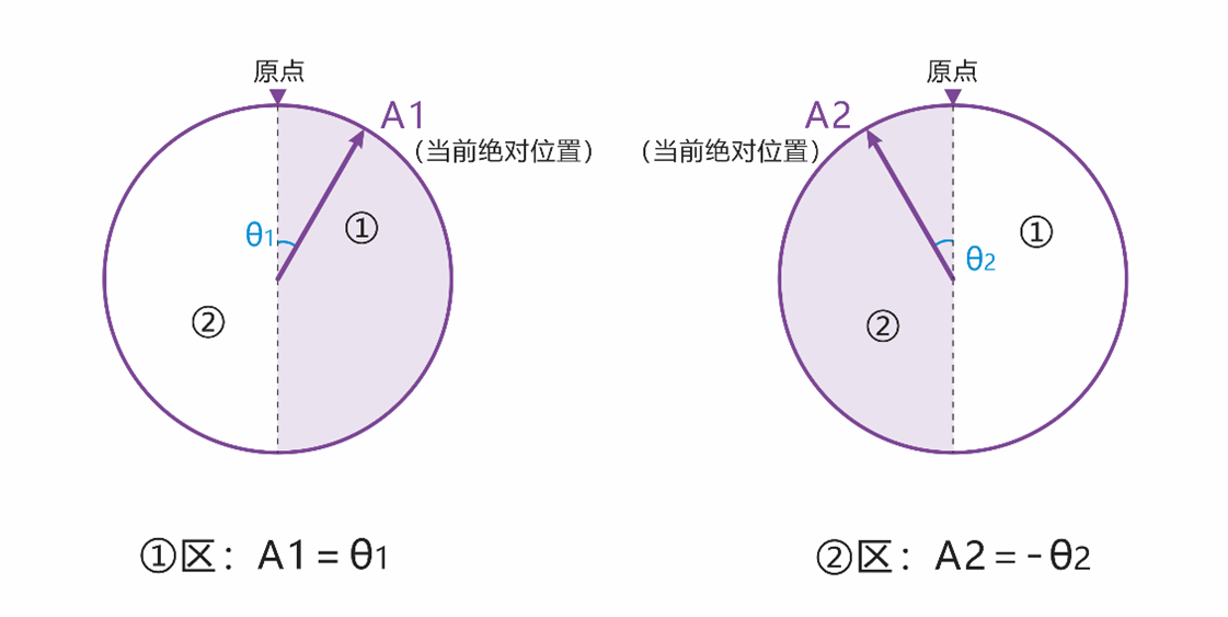
As shown in the figure, the current angle at point A1 is 6,880°, and the angle after reset is θ1. The current angle at point A2 is 6,800°, and the angle after reset is -θ2.
Power-off Angle Memory
- After power-off, if the servo angle does not change, the current angle read after power-on remains unchanged. (For example, if point A is 6,800° before power-off and the angle does not change during power-off, the servo remains at point A, and the read angle after power-on is still 6,800°.)
- After power-off, if the servo angle changes due to external force, the angle read after power-on will fall within ±180° of the memorized angle.
Note
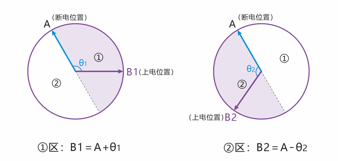
As shown in the figure, point A is 6,800° before power-off. If the servo is rotated by external force during power-off and finally stops at point B1, the angle read after power-on is 6,920°; if it stops at point B2, the read angle is 6,680°.
9.5 Damping Mode
Allows the servo to be moved to different angle positions under external force while maintaining a damping effect. The damping coefficient can be customized.
| Command ID | Command Name | Parameters |
|---|---|---|
| 09 (0x09) | Damping Control | Operating power (mW) |
9.6 Stop Commands
- Select the appropriate stop-command type according to motion-control requirements. See the table below for available types.
- Stop commands can also be used to restore normal operation after stall protection is triggered.
- When the servo is in release-torque state, sending the "Hold Torque" command rebuilds torque from the current position.
| Command ID | Command Name | Description |
|---|---|---|
| 24 (0x18) | Release Torque | Stops motion and releases holding torque. |
| 24 (0x18) | Hold Torque | Stops motion and maintains holding torque, or rebuilds torque from a no-torque state. |
| 24 (0x18) | Hold Damping | Stops motion and enters damping mode, allowing external force to adjust the angle. |
9.7 Synchronous Commands
- A single command can include control instructions for multiple servos, making it suitable for coordinated multi-servo motion.
- Each servo matches its own parameters in the command content through its unique ID, and only parses and responds to control information associated with that ID.
- After all servos receive the command, they begin executing their respective instructions simultaneously to achieve synchronized motion.
| Command ID | Command Name | Description |
|---|---|---|
| 25 (0x19) | Synchronous Command | - |
9.8 Asynchronous Commands
- Asynchronous commands consist of two parts: the Asynchronous Write Command and the Asynchronous Execute Command.
- Buffered motion commands remain stored until they are rewritten or power is removed, and are not overwritten or cleared by the execution of other commands.
- After an asynchronous command is triggered, its related parameters are cleared automatically and are not retained.
| Command ID | Command Name | Description |
|---|---|---|
| 18 (0x12) | Asynchronous Write Command | Writes the target motion command into the servo register buffer without executing it immediately. |
| 19 (0x13) | Asynchronous Execute Command | Triggers buffered asynchronous motion commands together, enabling synchronized execution across multiple servos. |
9.9 Status Readback / Data Monitoring
Used to obtain servo operating status and key parameters for configuration, inspection, and real-time display in PC software.
| Command ID | Command Name | Description |
|---|---|---|
| 03 (0x03) | Data Read | Reads individual servo status parameters or configuration parameters and returns the corresponding values. |
| 22 (0x16) | Data Monitoring | Returns complete status data, including voltage, current, power, temperature, status flags, angle, and turn count. |
9.10 Set Zero Point
Sets the current servo position as the zero point. This is commonly used for post-assembly zero calibration and provides a unified motion reference for control algorithms.
| Command ID | Command Name | Parameters |
|---|---|---|
| 23 (0x17) | Set Zero Point | Servo ID / reset = 0 |
10. More Resources
-
Used to connect bus servos to a PC or other main controller for communication configuration and data interaction.
-
Provides ID editing, real-time control across multiple operating modes, parameter configuration, status monitoring, and firmware upgrade.
-
Covers communication protocols, control logic, parameter configuration, and troubleshooting guidance for engineering use.